
This article was originally published in Le Bulletin Electrosuisse (February 2023 Edition).
The rapid evolution of thermal networks is an essential factor in the strategies developed to achieve the carbon reduction goals set for 2050. A CO2-based anergy network such as the one installed on the Energypolis campus in Sion delivers an efficient and cost-effective solution for many applications where a standard water-based network is not feasible.
One quarter of global greenhouse gas emissions originate from energy systems used to heat or cool buildings. Consequently, this sector has a key part to play in the transition towards a carbon-free world. Its role is all the more important because energy demand related to heating and air-conditioning systems is continuously increasing, whereas the rate of building renovations (<1%) is substantially below the targets set by the Swiss Federal government.
However, reducing carbon emissions from heating and cooling systems in dense urban environments presents a real challenge. Given their high density, these areas are suitable for installing energy networks to deliver heat to consumers in urban centres from peripheral renewable sources, which are often easier to exploit. Nevertheless, practice shows that districts with higher densities are subject to more restrictions on network installations (underground congestion, paved roads, problems of ensuring traffic flows while work is in progress, etc.). CO2-based anergy networks will be able to provide solutions for some of these challenges in future years.
What is an anergy network?
Anergy network technology has seen considerable development over the last 15 years. An anergy network (or loop) is a low-temperature thermal network (between 3 and 15°C) that offers heating services (via heat pumps) and cooling services (by direct cooling). These networks are particularly suitable for making efficient use of heat from the environment (lakes, rivers, groundwater, geothermal energy, etc.) and of waste heat, by taking advantage of synergies between heating and cooling demands. In this case, the low-temperature heat is transferred directly from the cooling consumers (refrigeration, cooling for IT equipment or process cooling, etc.) to the heating consumers (heat pumps).
The anergy networks that are currently operated use water in the liquid phase as the transfer fluid. To ensure compatibility not only with the temperature regimes imposed by air conditioning but also with those required by heat pumps, a small temperature difference is required between the two lines of the network (generally between 3 and 6°C): this results in a low volumetric energy density in the order of 3.3 to 6.6 kWh of low-temperature thermal energy per m3 of water transferred. This low density requires pipe diameters, excavations, and civil engineering works on a scale appropriate to the thermal power involved. The same applies to the electricity consumption of the pumps used to circulate the water in the network.
Benefits of a CO2-based anergy network
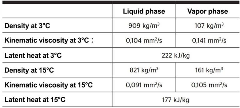
By exploiting the latent heat of evaporation/condensation of a fluid rather than its sensible heat, it becomes possible to supply the heat pumps and cold exchangers of an anergy network while significantly increasing its energy density and, consequently, reducing its footprint. For this purpose, the fluid used must have – at the temperature of the anergy network (3 to 15°C) – a high latent heat of evaporation/condensation as well as high densities and low viscosities for each of the liquid and gas phases.
CO2 offers these characteristics (table 1). If we consider the average density for the gas and liquid phases, the low-temperature volumetric thermal energy density is between 24.1 and 31.3 kWh per m3 of CO2 transferred, i.e., 3.6 to 9.5 times higher than the value for water. If all hydraulic constraints are considered, the footprint of a CO2 anergy system is about 2 to 3 times smaller than that of an equivalent water-based system. A reduction on this scale also has a beneficial effect on the complexity of the installation work, which is greatly simplified because the components to be assembled are smaller and lighter. Consequently, the excavation work required is far less extensive. These advantages are counterbalanced by the relatively high pressure of the CO2. At the network temperatures that apply here, the pressure is between 38 and 51 bar.
Accelerated development
Two characteristic features have made it possible to accelerate and scale this technology. Firstly, CO2 has been used as a refrigerant since the end of the 19th century. As for other natural fluids such as propane or ammonia, its use was abandoned in the 1930s to make way for fluids that were later found to be harmful to the ozone layer (ozone depletion potential, ODP) and which have a high environmental impact (global warming potential, GWP).
Nowadays, CO2 is once again attracting great interest and is used in industrial and commercial refrigeration thanks to its low environmental impact and to the high efficiency levels of machines available on the market. More than 40,000 CO2-based commercial cooling/refrigeration systems were operating in Europe at the end of 2021 (in supermarkets, ice rinks, fruit and vegetable warehouses, etc.) [1]. This accelerated introduction of CO2 for refrigeration purposes makes it easier to integrate existing components into the construction of a CO2 network such as the one on the Energypolis campus in Sion – all the more so because the same standards apply to the substations and the machines.
Secondly, the petrochemical industry developed flexible pipes made of reinforced thermoplastic material, which enable the transportation of fluids at operating pressures in excess of 100 bar. Thanks to the two points mentioned above, the current level of technological development already makes it possible to construct installations with several MW of thermal power.
A demonstrator on the Energypolis campus site
Various research projects, mainly undertaken at the Institute of Mechanical Engineering of the Swiss Federal Institute of Technology Lausanne (EPFL) between 2008 [2] and 2019 [3–7] have made it possible to develop the bases for implementing a network of significant size. ExerGo’s development work and competence in the realisation of the thermoplastic pipe network, Zero-C’s acknowledged expertise in the construction of CO2 installations, OIKEN’s provision of a connection to the renewable heat source (groundwater), together with project leadership and management of integration into the buildings by the University of Applied Sciences and Arts of Western Switzerland (HES-SO Valais), have created the favourable conditions required for the successful implementation of a CO2-based heating and cooling distribution network demonstrator on the new site of the Energypolis campus at Sion, in the canton of Valais.
This installation aims to demonstrate the validity, reliability, and functional safety of the concept in its final form under real operating conditions, and to evaluate its performance in terms of energy efficiency and economic aspects.
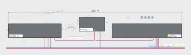
The Sion demonstrator was installed as a redundant system alongside the district heating and cooling networks (DHN and DCN) which already supply the buildings (figure 1). This configuration offers maximum flexibility for the various performance tests because it enables the demonstrator to provide heating and cooling services, but the buildings do not depend on it to supply their heating and cooling.
More details about the configuration
The demonstrator comprises a central plant (balancing unit) the role of which is to extract heat from the thermal source available in the cold season (or, respectively, to inject heat into the source during the hot season), three substations – consumers of heating and/or cooling – and the CO2 network as such, which links the substations to the central plant (figure 2).
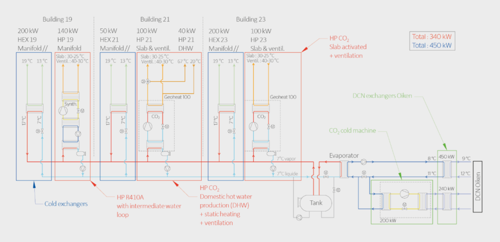
The central plant consists of a heat exchanger between the CO2 network and the renewable energy source (in this case, the groundwater connected via the DCN) and a buffer tank to equalise the network’s overall energy balance.
The network itself consists of a liquid-state CO2 line and a gaseous-state CO2 line; the CO2 circulates in flexible pipes made of composite materials that can withstand pressures of more than 100 bar. The liquid line is under higher pressure than the gas line. The pressure difference between the lines (of the order of 1 to 2 bar) ensures the supply to the heat exchangers used for direct cooling – i.e., without the need to use cooling machines.
Each of the three substations (one per building) uses a heat exchanger to supply cooling and a heat pump to produce the temperature required for heating and domestic hot water (Figure 2). A substation only requires the network to supply the difference between its energy requirements for heating and cooling. In a theoretical example where the building has perfectly balanced cooling and heating demands, it will have no dependency on the network. The same applies to all the substations: if the net heating and cooling demands for all the buildings are zero, the central plant does not need to be supplied from its thermal source.
How the system functions
The total installed thermal power is 340 kW for heating and 450 kW for cooling. In winter, the heat pumps extract heat from the network by condensing the gaseous CO2 and conveying the liquid CO2 produced to the central plant. The central plant compensates for the deficit of gaseous CO2 by evaporating the surplus of liquid CO2 with heat extracted from the groundwater.
In summer, the cooling circuit evacuates its heat by evaporating the liquid CO2 from the network and conveys the gaseous CO2 produced to the central plant. The central plant then compensates for the deficit of liquid CO2 by condensing the surplus of gaseous CO2 with the heat released in the groundwater. A cooling machine has been installed in the central plant for demonstration purposes, to allow simulation of various source temperatures (e.g. river, groundwater or lake).
Towards optimising energy performance
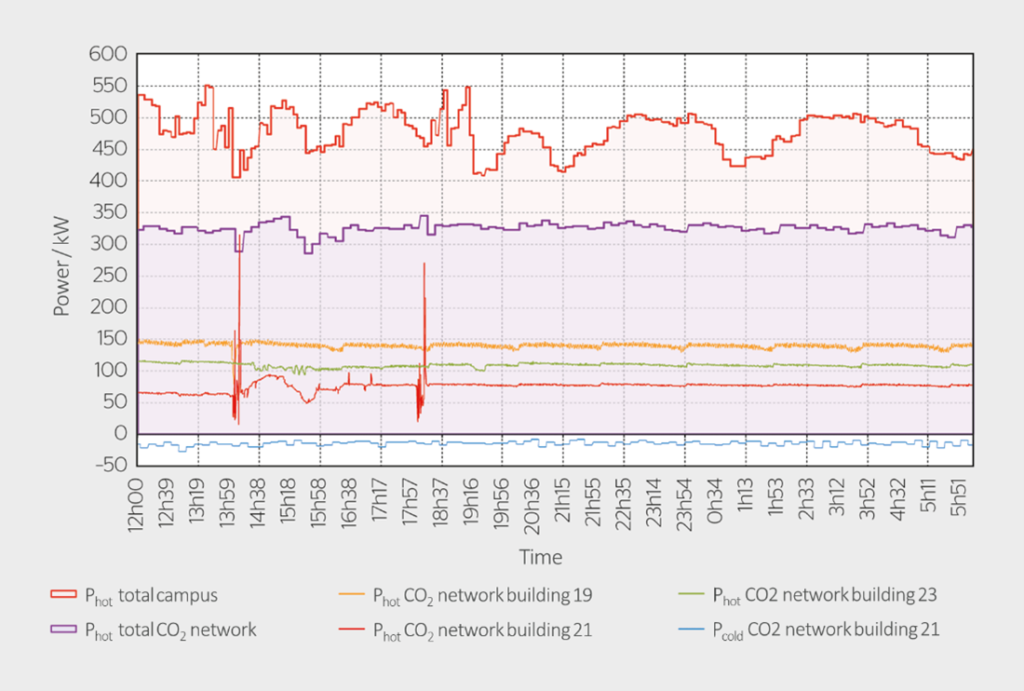
The demonstrator began operating in cooling mode in May 2022, and then in heating mode in November 2022. As Figure 3 shows, it is already able to meet over 50% of the site’s thermal requirements, and to take advantage of the anergy effect – i.e., simultaneous production of heat and cold (in this case via the server room). Now that this demonstration of feasibility (proof of concept) has been established, current research efforts are focused on measuring its energy performance and on finding technical solutions (typically: for management of the installations) which will enable improvements.
References
[1] r744.com/atmosphere-europe-natural-refrigerant-technologies-seen-as-good-investment/
[2] C. Weber, “Multi-objective design and optimization of district energy systems including polygeneration energy conversion“, EPFL thesis no. 4018, 2008.
[3] S. Henchoz, “Potential of refrigerant based district heating and cooling networks“, EPFL thesis no. 6935, 2016.
[4] P. Chatelan, “Potentiels thermo-économiques comparés de réseaux avancés fonctionnant au CO2 et à l’eau“, practical Masters project undertaken at the EPFL Industrial Energy Laboratory, 2014.
[5] S. Henchoz, C. Weber, F. Maréchal, D. Favrat, “Performance and profitability perspectives of a CO2 based district energy network in Geneva’s city center“, Energy, Vol. 85, p. 221-235, 2015.
[6] S. Henchoz, P. Chatelan, F. Maréchal, D. Favrat, “Key energy and technological aspects of three innovative district energy networks“, Energy, Vol. 117, p. 465-477, 2016.
[7] R.-A. Suciu, “5th generation district energy systems for low carbon cities“, EPFL thesis no. 7332, 2019.
Authors
Cédric Dorsaz is a senior academic associate at HES-SO Valais.
- HES-SO Valais-Wallis, 1950 Sion
- dorsaz@hes-so.ch
Samuel Henchoz is the CTO of ExerGo SA.
- ExerGo SA, 1400 Yverdon-les-Bains
- henchoz@exergo.com
Alberto Mian is the CEO of ExerGo SA.
- alberto.mian@exergo.com
Jessen Page is a professor at HES-SO Valais.
- jessen.page@hes-so.ch
Acknowledgements
The authors wish to thank the Swiss Federal Office of Energy (SFOE) for funding the “CO2 network demonstration” project through its pilot and demonstration programme, the Zero-C and OIKEN companies, and professor François Maréchal of EPFL, for their essential contributions to the success of this project.